
Page 95 - Demo
P. 95
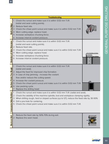
93GENERAL PURPOSE DRILLINGTroubleshootingBuilt-Up Edge1 Check the runout and make sure it is within 0.02 mm T.I.R. (radial and axial cutting points).2 Reduce feed rate.3 Check the chisel point runout and make sure it is within 0.02 mm T.I.R.4 Worn cutting edge. replace head.5 Increase workpiece chucking force.6 Increase internal coolant pressure. Deviation of Hole Tolerance1 Check the runout and make sure it is within 0.02 mm T.I.R. (radial and axial cutting points).2 Reduce feed rate.3 Check the chisel point runout and make sure it is within 0.02 mm T.I.R.4 Worn cutting edge. replace head.5 Increase workpiece chucking force.6 Increase internal coolant pressure.%u00d8 > D nominal + 0.15mm%u00d8 < D nominal - 0.03mmD nominalSurface Finish Too Rough1 Check the runout and make sure it is within 0.02 mm T.I.R. (radial and axial).2 Adjust the feed for improved chip formation.3 In case of chip jamming - increase the coolant flow and/or reduce the cutting speed.4 Increase the coolant pressure.5 Check the chisel point runout and make sure it is within 0.02 mm T.I.R.6 Use pecking cycle.7 Replace the drilling headRaInaccurate Hole Position1 Check the runout and make sure it is within 0.02 mm T.I.R. (radial and axial).2 Check the stability of the machine spindle, tool and workpiece clamping rigidity.3 When drilling rough, hard or sloped surfaces (up to 12%u00b0), reduce the feed rate by 30-50% 4 Drill a pre-hole for centering.5 Check the chisel point runout and make sure it is within 0.02 mm T.I.R.Burrs on Exit1 Reduce the feed rate by 50%-70% during exit.2 Replace the worn head.
