
Page 116 - Demo
P. 116
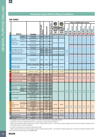
114 ISCAR GENERAL PURPOSE DRILLINGIndexable Insert Drills Cutting ConditionsDR-TWIST ISOMaterial Condition Tensile Strength [N/mm2] Hardness HB Material Group No.Feed vs. Drill Diameter mm/revDR-04 AL/DT/HDDR-05 GF/DT/AL/HDDR-06 GF/DT/AL/HDDR-07 GF/DT/AL/HDDR-09/10 GF/DT/AL/HDDR-11/12 GF/DT/AL/HDDR-14/16 GF/DT/ALCutting Speed /HD(1)Vc m/minIC808/ 908 externalVc m/minIC8080 /9080 externalPnon-alloy steel and cast steel, free cutting steel<0.25% C annealed 420 125 1 200-300 260-3900.04-0.080.02-0.060.06-0.100.10-0.150.04-0.080.07-0.120.10-0.160.04-0.080.08-0.120.12-0.180.05-0.100.10-0.150.14-0.220.05-0.100.12-0.160.15-0.250.08-0.150.14-0.170.16-0.260.08-0.15%u22650.25% C annealed 650 190 2<0.55% C quenched and tempered 850 250 3150-200 190-260%u22650.55% Cannealed 750 220 4quenched and tempered 1000 300 5 0.06-0.100.10-0.140.04-0.080.07-0.120.10-0.150.04-0.080.08-0.120.10-0.160.05-0.100.10-0.140.14-0.200.05-0.100.12-0.150.14-0.220.08-0.150.14-0.160.15-0.240.08-0.15low alloy and cast steel (less than 5% of alloying elements)annealed 600 200 6 150-220 190-290quenched and tempered930 275 71000 300 8 120-180 160-2301200 350 9high alloyed steel, cast steel and tool steelannealed 680 200 10 120-190 160-250 0.06-0.100.10-0.140.08-0.1120.06-0.100.10-0.140.08-0.1120.06-0.100.10-0.140.08-0.1120.08-0.120.12-0.180.096-0.1440.10-0.150.14-0.200.112-0.1600.14-0.170.16-0.240.128-0.192quenched and tempered 1100 325 11 100-160 210-310stainless steel and cast steelferritic / martensitic 680 200 12160-240 210-3100.06-0.100.048-0.080.06-0.100.048-0.080.06-0.120.048-0.0960.08-0.120.064-0.0960.10-0.140.08-0.1120.12-0.200.096-0.160martensitic 820 240 13M stainless steel and cast steel austenitic, duplex 600 180 14 160-240 210-310 0.04-0.080.06-0.100.06-0.100.06-0.120.08-0.120.10-0.140.12-0.20Kgray cast iron (GG) ferritic / pearlitic 180 15 150-250 190-3200.08-0.160.10-0.220.10-0.220.10-0.220.15-0.250.18-0.300.20-0.34pearlitic / martensitic 260 16nodular cast iron (GGG) ferritic 160 17120-180 160-230 pearlitic 250 18malleable cast iron ferritic 130 19pearlitic 230 20Naluminum-wrought alloys not hardenable 60 21150-300 190-390 0.08-0.240.12-0.250.12-0.250.12-0.250.20-0.300.2-0.350.28-0.45hardenable 100 22aluminumcast alloys%u226412% Si not hardenable 75 23hardenable 90 24>12% Si high temperature 130 25copper alloys>1% Pb free cutting 110 26brass 90 27electrolytic copper 100 28non metallicduroplastics, fiber plastics70Shore D 29hard rubber 55Shore D 30Shigh temperature alloysFe based annealed 200 3120-50 30-600.03-0.070.04-0.080.04-0.080.05-0.090.07-0.100.08-0.120.10-0.14hardened 280 32Ni or Co basedannealed 250 33hardened 350 34cast 320 35titanium alloyspure 400 190 36alpha+beta alloys, 50-60 60-80hardened 1050 310 37Hhardened steel hardened 55 HRC 38 20-50 30-60 0.04-0.080.05-0.080.05-0.080.06-0.090.07-0.100.08-0.120.10-0.14hardened 60 HRC 39chilled cast iron cast 400 40cast iron hardened 55 HRC 41%u2022 This table refers to 2/3xD drill ratio usage. %u2022 For 4xD ratio decrease cutting data by 15% %u2022 Chipformer should be selected based on our geometry range recommendations %u2022 When using external coolant supply only, reduce cutting speed by 10% %u2022 Use internal coolant supply when machining austenitic stainless steel %u2022 This table refers to 2/3xD drill lengths. %u2022 For 4xD and 5XD drills, decrease cutting data by 15% %u2022 When using only external coolant supply, reduce cutting speed by 10% %u2022 Use internal coolant supply when machining austenitic stainless steel (1) Central insert should always be IC808/IC908
